Traffic Manager
- What is it?
- Architecture
- Using the Traffic Manager
- Hybrid physics mode
- Running multiple Traffic Managers
- Other considerations
- Summary
What is it?
The Traffic Manager, TM for short, is the module in charge of controlling vehicles inside the simulation. It is built on top of the CARLA API in C++. Its goal is to populate the simulation with realistic urban traffic conditions. Users can customize some behaviours, for example to set specific learning circumstances. Every TM controls vehicles registered to it by setting autopilot to true, and is accounting for the rest by considering them unregistered.
Structured design
The TM is built on the client-side of the CARLA architecture. It replaces the server-side autopilot. The execution flow is divided in stages with independent operations and goals. This facilitates the development of phase-related functionalities and data structures, while also improving computational efficiency. Each stage runs on a different thread. Communication with the rest is managed through synchronous messaging between the stages.The information flows only in one direction.
User customization
Users must have some control over the traffic flow by setting parameters that allow, force or encourage specific behaviours. Users can change the traffic behaviour as they prefer, both online and offline. For example they could allow a car to ignore the speed limits or force a lane change. Being able to play around with behaviours is a must when trying to simulate reality. It is necessary to train driving systems under specific and atypical circumstances.
Architecture
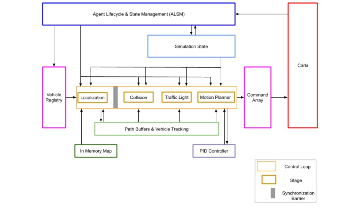
The previous diagram is a summary of the internal architecture of the Traffic Manager. The inner structure of the TM can be easily translated to code, and each relevant component has its equivalent in the C++ code (.cpp files) inside LibCarla/source/carla/trafficmanager. The functions and relations of these components are explained in the following sections.
Nevertheless, the logic of it can be simplified as follows.
1. Store and update the current state of the simulation.
First of all, the ALSM (Agent Lifecycle & State Management) scans the world to keep track of all the vehicles and walkers present in it, and clean up entries for those that no longer exist. All the data is retrieved from the server, and then passed to the stages. In such way, calls to the server are isolated in the ALSM, and these information can be easily accessible onwards. The vehicle registry contains an array with the registered vehicles, and a list with the rest of vehicles and pedestrians. The simulation state stores in cache the position and velocity and some additional information of all the cars and walkers.
2. Calculate the movement of every registered vehicle.
The main goal of the TM is to generate viable commands for all the vehicles in the vehicle registry, according to the simulation state. The calculations for each vehicle are done separatedly. These calculations are divided in different stages. The control loop makes sure that all the calculations are consistent by creating synchronization barriers in between stages. No one moves to the following stage before the calculations for all the vehicles are finished in the current one. Each vehicle has to go through the following stages.
2.1 - Localization Stage.
TM vehicles do not have a predefined route, and path choices are taken randomly at junctions. Having this in mind, the In-Memory Map simplifies the map as a grid of waypoints, and a near-future path to follow is created as a list of waypoints ahead. The path of every vehicle will be stored by the PBVT component (Path Buffers & Vehicle Tracking), so that these can be easily accessible and modified in future stages.
2.2 - Collision Stage.
During this stage, bounding boxes are extended over the path of each vehicle to identify potential collision hazards, which are then managed when necessary.
2.3 - Traffic Light Stage
Similar to the Collision Stage, this stage identifies potential hazards that affect the path of the vehicle according to traffic light influence, stop signs, and junction priority.
2.4 - Motion Planner Stage.
Once a path has been defined, this stage computes vehicle movement. A PID controller is used to determine how to reach the target values. This movement is then translated into an actual CARLA command to be applied.
3. Apply the commands in the simulation.
Finally, the TM has calculated the next command for every vehicle, and now it is only a matter of applying them. All the commands are gathered by the command array, and sent to the CARLA server in a batch so that they are applied in the same frame.
And thus the cycle is concluded. The TM follows this logic on every step of the simulation. For a better understanding of the role that each component plays, this section includes an in-depth description of each of them.
ALSM
ALSM stands for Agent Lifecycle and State Management. First step in the logic cycle. Provides context over the current state of the simulation.
- Scans the world to keep track of all the vehicles and walkers in it, their positions and velocities. If physics are enabled, the velocity is retrieved by Vehicle.get_velocity(). Instead, if physics are disabled, the velocity is computed using the history of position updates over time.
- Stores the position, velocity and additional information (traffic light influence, bounding boxes, etc) of every vehicle and walker in the simulation state module.
- Updates the list of registered vehicles stored by the vehicle registry.
- Updates entries in the control loop and PBVT modules to match the list of registered vehicles.
Related .cpp files: ALSM.h, ALSM.cpp.
Command array
Last step in the TM logic cycle. Receives commands for all the registered vehicles and applies them.
- Receives a series of carla.VehicleControl from the Motion Planner Stage.
- Constructs a batch for all the commands to be applied during the same frame.
- Sends the batch to the CARLA server. Either apply_batch() or apply_batch_synch() in carla.Client will be called, depending if the simulation is running in asynchronous or synchronous mode, respectively.
Related .cpp files: TrafficManagerLocal.cpp.
Control loop
Manages the process of calculating the next command for all the registered vehicles, so that these are done in synchrony.
- Receives from the vehicle registry an array of the vehicles registered to the TM.
- Loops over said array, performing calculations per vehicle separatedly.
- These calculations are divided in a series of stages.
- Synchronization barriers are placed between stages so that consistency is guaranteed. Calculations for all vehicles must finish before any of them moves to the next stage, ensuring that all vehicles are updated in the same frame.
- Coordinates the transition between stages so that all the calculations are done in sync.
- When the last stage (Motion Planner Stage) finishes, the command array is sent to the server. In this way, there are no frame delays between the calculations of the control loop, and the commands being applied.
Related .cpp files: TrafficManagerLocal.cpp.
In-Memory Map
Helper module contained by the PBVT and used during the Localization Stage.
- Discretizes the map into a grid of waypoints.
- Includes waypoints in a specific data structure with more information to connect waypoints and identify roads, junctions...
- Identifies these structures with an ID that is used to quickly spot vehicles in nearby areas.
Related .cpp files: InMemoryMap.cpp and SimpleWaypoint.cpp.
PBVT
PBVT stands for Path Buffer and Vehicle Tracking. This data structure contains the expected path for every vehicle so that it can be easily accessible during the control loop.
- Contains a map of deque objects with an entry per vehicle.
- For each vehicle, contains a set of waypoints describing its current location and near-future path.
- Contains the In-Memory Map that will be used by the Localization Stage to relate every vehicle to the nearest waypoint, and possible overlapping paths.
PID controller
Helper module that performs calculations during the Motion Planner Stage.
- Using the information gathered by the Motion Planner Stage, estimates the throttle, brake and steering input needed to reach a target value.
- The adjustment is made depending on the specific parameterization of the controller, which can be modified if desired. Read more about PID controllers to learn how to do it.
Related .cpp files: PIDController.cpp.
Simulation state
Stores information about the vehicles in the world so that it can be easily accessible during all the process.
- Receives the current state of all vehicles and walkers in the world from the ALSM, including their position, velocity and some additional information (such as traffic light influence and state). It also stores some additional information such as whereas these vehicles are under the inffluence of a traffic light and what is the current state of said traffic light.
- Stores in cache all the information so that no additional calls to the server are needed during the control loop.
Related .cpp files: SimulationState.cpp, SimulationState.h.
Stages
Stage 1- Localization Stage
First stage in the control loop. Defines a near-future path for registered vehicles.
- Obtains the position and velocity of all the vehicles from simulation state.
- Using the In-Memory Map, relates every vehicle with a list of waypoints that describes its current location and near-future path, according to its trajectory. The faster the vehicle goes, the larger said list will be.
- The path is updated according to planning decisions such as lan changes, speed limit, distance to leading vehicle parameterization, etc.
- The PBVT module stores the path for all the vehicles.
- These paths are compared with each other, in order to estimate possible collision situations. Results are passed to the following stage: Colllision stage.
Related .cpp files: LocalizationStage.cpp and LocalizationUtils.cpp.
Stage 2- Collision Stage
Second stage in the control loop. Triggers collision hazards.
- Receives a list of pairs of vehicles with possible overlapping paths from the Localization Stage.
- For every pair, extends bounding boxes along the path ahead (geodesic boundaries), to check if they actually overlap and the risk of collision is real.
- Hazards for all the possible collisions will be sent to the Motion Planner Stage to modify the path accordingly.
Related .cpp files: CollisionStage.cpp.
Stage 3- Traffic Light Stage
Third stage in the control loop. Triggers hazards to follow traffic regulations such as traffic lights, stop signs, and priority at junctions.
- If the vehicle is under the influence of a yellow or red traffic light, or a stop sign, sets a traffic hazard.
- If the vehicle is in a non-signalized junction, a bounding box is extended along its path. Vehicles with overlapping paths follow a FIFO order to move, and waits are set to a fixed time.
Related .cpp files: TrafficLightStage.cpp.
Stage 4- Motion Planner Stage
Fourth and last stage in the control loop. Generates the CARLA command that will be applied to the vehicle.
- Gathers all the information so far: position and velocity of the vehicles (simulation state), their path (PBVT), hazards (Collision Stage and Traffic Light State).
- Makes high-level decisins about how should the vehicle move, for example computing the brake needed to prevent a collision hazard. A PID controller is used to estimate behaviors according to target values.
- Translates the desired movement to a carla.VehicleControl that can be applied to the vehicle.
- Sends the resulting CARLA commands to the command array.
Related .cpp files: MotionPlannerStage.cpp.
Vehicle registry
Keeps track of all the vehicles and walkers in the simulation.
- The ALSM scans the world and passes an updated list of walkers and vehicles.
- Vehicles registered to the TM are stored in a separated array that will be iterated on during the control loop.
Related .cpp files: MotionPlannerStage.cpp.
Using the Traffic Manager
General considerations
First of all there are some general behaviour patterns the TM will generate that should be understood beforehand. These statements are inherent to the way the TM is implemented:
- Vehicles are not goal-oriented they follow a trajectory and whenever approaching a junction, choose a path randomly. Their path is endless, and will never stop roaming around the city.
- Vehicles' target speed is 70% their current speed limit: unless any other value is set.
- Junction priority does not follow traffic regulations: the TM has a priority system to be used while junction complexity is solved. This may cause some issues such as a vehicle inside a roundabout yielding to a vehicle trying to get in.
The TM provides a set of possibilities so the user can establish specific behaviours. All the methods accessible from the Python API are listed in the documentation. However, here is a brief summary of what the current possibilities are.
| General: | 1. Use a carla.Client to create a TM instance connected to a port. 2. Retrieve the port where a TM is connected. |
| Safety conditions: | 1. Set a minimum distance between stopped vehicles (for a vehicle or all of them). This will affect the minimum moving distance. 2. Set an intended speed regarding current speed limitation (for a vehicle or all of them). 3. Reset traffic lights. |
| Collision managing: | 1. Enable/Disable collisions between a vehicle and a specific actor. 2. Make a vehicle ignore all the other vehicles. 3. Make a vehicle ignore all the walkers. 4. Make a vehicle ignore all the traffic lights. |
| Lane changes: | 1. Force a lane change disregarding possible collisions. 2. Enable/Disable lane changes for a vehicle. |
| Hybrid physics mode: | 1. Enable/Disable the hybrid physics mode. 2. Change the radius where physics are enabled. |
Creating a Traffic Manager
A TM instance can be created by any carla.Client specifying the port that will be used. The default port is 8000.
tm = client.get_trafficmanager(port)
Now the TM needs some vehicles to be in charge of. In order to do so, enable the autopilot mode for the set of vehicles to be managed. Retrieve the port of the TM object that has been created. If no port is provided, it will try to connect to a TM in the default port, 8000. If the TM does not exist, it will create it.
tm_port = tm.get_port()
 for v in vehicles_list:
     v.set_autopilot(True,tm_port)
Note
In multiclient situations, creating or connecting to a TM is not that straightforward. Take a look into the other considerations section to learn more about this.
The script spawn_npc.py in /PythonAPI/examples creates a TM instance in the port passed as argument and registers every vehicle spawned to it by setting the autopilot to True on a batch.
traffic_manager = client.get_trafficmanager(args.tm-port)
tm_port = traffic_manager.get_port()
...
batch.append(SpawnActor(blueprint, transform).then(SetAutopilot(FutureActor, True,tm_port)))
...
traffic_manager.global_percentage_speed_difference(30.0)
Setting a Traffic Manager
The following example creates an instance of the TM and sets a dangerous behaviour for a specific car that will ignore all traffic lights, leave no safety distance with the rest and drive at 120% its current speed limit.
tm = client.get_trafficmanager(port)
tm_port = tm.get_port()
for v in my_vehicles:
  v.set_autopilot(True,tm_port)
danger_car = my_vehicles[0]
tm.ignore_lights_percentage(danger_car,100)
tm.distance_to_leading_vehicle(danger_car,0)
tm.vehicle_percentage_speed_difference(danger_car,-20)
Now, here is an example that registers that same list of vehicles but instead is set to conduct them with a moderate behaviour. The vehicles will drive at 80% their current speed limit, leaving at least 5 meters between them and never perform a lane change.
tm = client.get_trafficmanager(port)
tm_port = tm.get_port()
for v in my_vehicles:
  v.set_autopilot(True,tm_port)
danger_car = my_vehicles[0]
tm.global_distance_to_leading_vehicle(5)
tm.global_percentage_speed_difference(80)
for v in my_vehicles:
  tm.auto_lane_change(v,False)
Stopping a Traffic Manager
The TM is not an actor that needs to be destroyed, it will stop when the corresponding client does so. This is automatically managed by the API so the user does not have to take care of it.
However, it is important that when shutting down a TM, the vehicles registered to it are destroyed. Otherwise, they will stop at place, as no one will be conducting them. The script spawn_npc.py does this automatically.
Warning
Shutting down a TM-Server will shut down the TM-Clients connecting to it. To learn the difference between a TM-Server and a TM-Client read about multiclient and multiTM.
Hybrid physics mode
In hybrid mode, either all vehicle physics can be disabled, or enabled only in a radius around an ego vehicle with the tag hero. This feature removes the vehicle physics bottleneck from the simulator. Since vehicle physics are not active, all cars move by teleportation. This feature relies on Actor.set_simulate_physics(). However, not all the physics are disregarded. Basic calculations for a linear acceleration are maintained. By doing so, the position update, and vehicle speed still look realistic. That guarantees that when a vehicle enables or disables its physics, the transition is fluid.
The hybrid mode is disabled by default. There are two ways to enable it.
- TrafficManager.set_hybrid_phisics_mode(True) — This method will enable the hybrid mode for the Traffic Manager object calling it.
- Running
spawn_npc.pywith the flag--hybrid— The vehicles spawned will be registered to a Traffic Manager stated inside the script, and this will run with the hybrid physics on.
The are two parameters ruling the hybrid mode. One is the radius that states the proximity area around any ego vehicle where physics are enabled. The other is the vehicle with , that will act as center of this radius.
- Radius (default = 70 meters) — States the proximity area around the ego vehicle where physics are enabled. The value be changed with traffic_manager.set_hybrid_mode_radius(r).
- Ego vehicle — A vehicle tagged with
role_name='hero'that will act of the radius.- If there is none, all the vehicles will disable physics.
- If there are many, the radius will be considered for all of them. That will create different areas of influence with physics enabled.
The following example shows how the physics are enabled and disabled when hybrid mode is on. The ego vehicle is tagged with a red square. Vehicles with physics disabled are tagged with a blue square. When inside the area of influence stated by the radius, physics are enabled and the tag becomes green.
Running multiple Traffic Managers
Definitions
When working with different clients containing different TM, understanding inner implementation of the TM in the client-server architecture becomes specially relevant. There is one ruling these scenarios: the port is the key.
A client creates a TM by communicating with the server and passing the intended port to be used for said purpose. The port can either be stated or not, using the default as 8000.
- TM-Server — The port is free. This type of TM is in charge of its own logic, managed in
TrafficManagerLocal.cpp. The following code creates two TM-Servers. Each one connects to a different port, not previously used.
tm01 = client01.get_trafficmanager() # tm01 --> tm01 (p=8000)
tm02 = client02.get_trafficmanager(5000) # tm02(p=5000) --> tm02 (p=5000)
- TM-Client — The port is occupied by another TM. This instances are not in charge of their own logic. Instead, they ask for changes in the parameters of the TM-Server they are connected to in
TrafficManagerRemote.cpp. The following code creates two TM-Clients, that connect with the TM-Servers previously created.
tm03 = client03.get_trafficmanager() # tm03 --> tm01 (p=8000).
tm04 = client04.get_trafficmanager(5000) # tm04(p=5000) --> tm02 (p=5000)
Important
Note how the default creation of a TM uses always port=8000, and so, only the first time a TM-Server is created. The rest will be TM-Clients connecting to it.
The CARLA server keeps register of all the TM instances internally by storing the port and also the client IP (hidden to the user) that link to them. Right now there is no way to check the TM instances that have been created so far. A connection will always be attempted when trying to create an instance and it will either create a new TM-Server or a TM-Client.
Note
The class TrafficManager.cpp acts as a central hub managing all the different TM instances.
Multiclient
More than one TM instances created with the same port. The first will be a TM-Server. The rest will be TM-Clients connecting to it.
terminal 1: ./CarlaUE4.sh -carla-rpc-port=4000
terminal 2: python3 spawn_npc.py --port 4000 --tm-port 4050 # TM-Server
terminal 3: python3 spawn_npc.py --port 4000 --tm-port 4050 # TM-Client
MultiTM
Different TM instances with different ports assigned.
terminal 1: ./CarlaUE4.sh -carla-rpc-port=4000
terminal 2: python3 spawn_npc.py --port 4000 --tm-port 4050 # TM-Server A
terminal 3: python3 spawn_npc.py --port 4000 --tm-port 4550 # TM-Server B
Multisimulation
Multisimulation is when there are more than one CARLA server running at the same time. The TM declaration is not relevant. As long as the computational power allows for it, the TM can run multiple simulations at a time without any problems.
terminal 1: ./CarlaUE4.sh -carla-rpc-port=4000 # simulation A
terminal 2: ./CarlaUE4.sh -carla-rpc-port=5000 # simulation B
terminal 3: python3 spawn_npc.py --port 4000 --tm-port 4050 # TM-Server A connected to simulation A
terminal 4: python3 spawn_npc.py --port 5000 --tm-port 5050 # TM-Server B connected to simulation B
The concept of multisimulation is independent from the Traffic Manager itself. The example above runs two CARLA simulations in parallel, A and B. In each of them, a TM-Server is created independently from the other. Simulation A could run a Multiclient TM while simulation B is running a MultiTM, or no TM at all.
The only possible issue arising from this is a client trying to connect to an already existing TM which is not running on the selected simulation. In case this happens, an error message will appear and the connection will be aborted, to prevent interferences between simulations.
Other considerations
The TM is a module constantly evolving and trying to adapt the range of possibilities that it presents. For instance, in order to get more realistic behaviours we can have many clients with different TM in charge of sets of vehicles with specific and distinct behaviours. This range of possibilities also makes for a lot of different configurations that can get really complex and specific. For such reason, here are listed of considerations that should be taken into account when working with the TM as it is by the time of writing.
FPS limitations
The TM stops working properly in asynchronous mode when the simulation is under 20fps. Below that rate, the server is going much faster than the client containing the TM and behaviours cannot be simulated properly. For said reason, under these circumstances it is recommended to work in synchronous mode.
Important
The FPS limitations are specially relevant when working in the night mode.
Synchronous mode
TM-Clients cannot tick the CARLA server in synchronous mode, only a TM-Server can call for a tick.
If more than one TM-Server ticks, the synchrony will fail, as the server will move forward on every tick. This is specially relevant when working with the ScenarioRunner, which runs a TM. In this case, the TM will be subordinated to the ScenarioRunner and wait for it.
Warning
Disable the synchronous mode in the script doing the ticks before it finishes. Otherwise, the server will be blocked, waiting forever for a tick.
Summary
The Traffic Manager is one of the most complex features in CARLA and so, one that is prone to all kind of unexpected and really specific issues. The CARLA forum is open to everybody to post any doubts or suggestions, and it is the best way to keep track of issues and help the CARLA community to become greater. Feel free to login and join the community.